

4 Series B MSO Mixed Signal Oscilloscope
- ModelMSO44/MSO44B/MSO46/MSO46B
- AttributesMixed Signal Oscilloscope
- Category TEKTRONIX > 4 Series B MSO Mixed Signal Oscilloscope
- BrandTEKTRONIX
- DescriptionThe versatile 4 Series B MSO delivers the performance to tackle complex design challenges, with an intuitive user interface that operates the way you expect. With its newly upgraded processor system, this oscilloscope delivers accurate measurement results
Detailed Introduction Technical Documents
| Model | Analog Bandwidth | Analog Channels | Number of Digital Channels | Sampling Rate | Record Length |
|---|---|---|---|---|---|
| MSO44 | 200 MHz to 1.5 GHz | 4 | Up to 32 channels (optional) | 6.25GS/s | 31.25 M to 62.5 M points |
| MSO44B | 200 MHz to 1.5 GHz | 4 | Up to 32 (optional) | 6.25 GS/s | 31.25 M to 62.5 M |
| MSO46 | 200 MHz to 1.5 GHz | 6 | Up to 48 channels (optional) | 6.25GS/s | 31.25 M to 62.5 M points |
| MSO46B | 200 MHz to 1.5 GHz | 6 | Up to 48 (optional) | 6.25 GS/s | 31.25 M to 62.5 M |
Intensity (Digital)
Input Channels
4 or 6 FlexChannel® inputs
Each FlexChannel provides:
One analog signal, which can be displayed as waveform view, spectrum view1, or both simultaneously
8 digital logic inputs when using the TLP058 logic probe
Bandwidth (all analog channels)
200 MHz, 350 MHz, 500 MHz, 1 GHz, 1.5 GHz (upgradable)
Sampling Rate (All Analog/Digital Channels)
Real Time: 6.25 GS/s
Record Length (All Analog/Digital Channels)
Standard: 31.25 M points (Optional upgrade to 62.5 M points)
Waveform Capture Rate
>500,000 waveforms/sec
Vertical Resolution
12-bit ADC
Up to 16-bit in high resolution mode
Standard Trigger Types
Edge, Pulse Width, Runt, Timeout, Window, Logic, Setup & Hold, Rise/Fall Time, Parallel Bus, Sequence, Visual Trigger, Video (Optional), RF vs Time (Optional)
Auxiliary Trigger ≤300 VRMS (Edge trigger only)
Standard Analysis
Cursors: Waveform, V Bars, H Bars, V&H Bars
Measurements: 36
Spectrum View: Frequency domain analysis, independent control of frequency domain and time domain
FastFrameTM: Segmented memory acquisition mode, maximum trigger rate > 5,000,000 waveforms/sec
Graphs: Time trend, Histogram, Spectrum
Math: Basic waveform algebra, FFT and advanced formula editor
Search: Search any trigger criteria
Optional Analysis
Advanced Spectrum View
RF vs Time traces, triggering, spectrogram and IQ capture
Mask/Limit Testing
Advanced power measurement and analysis
Three-phase electrical analysis (MSO46 only)
Optional protocol trigger, decode and analysis
I2C、SPI、eSPI、I3C、RS-232/422/485/UART、SPMI、SMBus、CAN、CAN FD、LIN、FlexRay、SENT、PSI5、CXPI、、、、USB 2.0、eUSB2、Ethernet、EtherCAT、Audio、MIL-STD-1553、ARINC 429、Spacewire、、NRZ、Manchester、SVID、SDLC、1-Wire、MDIO and NFC
Arbitrary/Function Generator1
50 MHz Waveform Generation
Waveform Types: Arbitrary waveform, sine wave, square wave, pulse, sawtooth wave, triangle wave, DC level, Gaussian, Lorentz, exponential rise/fall, Sin(x)/x, random noise, haversine curve, ECG
Digital Voltmeter2
4-digit AC RMS, DC and DC+AC RMS Voltage Measurement
Trigger Frequency Counter2
8-digit
Display
13.3-inch (338 mm) Color TFT
HD (1920 x 1080) Resolution
Capacitive (Multi-Touch) Touch Screen
Connectivity
USB 2.0 Host, USB 2.0 Device (5 ports); LAN (10/100/1000 Base-T Ethernet); HDMI 3
Warranty
3 Years (Standard)
Dimensions
286.99 mm (11.299 in) Height x 450 mm (17.7 in) Width x 155 mm (6.1 in) Depth
Weight: < 7.6 kg (16.8 lbs)
Featuring an all-new touchscreen user interface with gesture pinch-to-zoom, high-definition display, and 4 or 6 FlexChannel® inputs (each channel can measure 1 analog signal or 8 digital signals), the 4 Series MSO is ready to tackle the tough challenges of today and tomorrow. It sets a new standard for performance, analysis, and overall user experience.
Never let a lack of channels delay your inspection and debugging process!
The 4 Series MSO is available in 4-channel and 6-channel models, equipped with a 13.3-inch HD (1,920 x 1,080) display that enables better visibility of complex systems. Many applications such as embedded systems, three-phase electronics, automotive electronics, power supply design, and DC-to-DC power converters, require observing more than 4 analog signals, test and characterize device performance, and debug extremely challenging system issues.
Most engineers have experienced this: when debugging a particularly tough problem that requires better visibility of the system and its status, their oscilloscope only offers two or four analog channels. Adding a second oscilloscope is very cumbersome: you have to align triggers, it is difficult to confirm the timing relationship between the two displays, and document management also becomes a problem.
You might expect a 6-channel oscilloscope to cost 50% more than a 4-channel model, but you'll be pleasantly surprised that our 6-channel oscilloscope is only ~20% more expensive than the 4-channel version. The additional analog channels pay for themselves quickly, because you can complete your current and future projects on schedule.
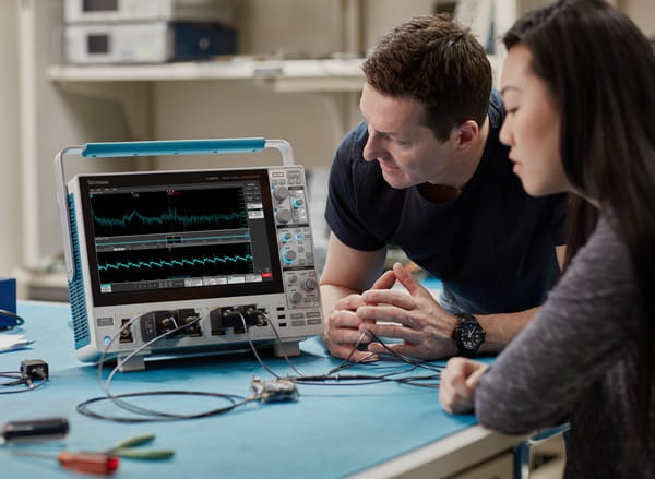
Voltage measurement on a switching power supply shows the ripple voltage on one of the power rails.
FlexChannel® technology enables greater flexibility and expands the system's observation capability
4 Series MSO redefines the standard for mixed signal oscilloscopes (MSO). With FlexChannel technology, each channel input can be configured as 1 analog channel, 8 digital logic inputs (using TLP058 logic probe), or simultaneous analog and spectrum views4 Each domain uses independent acquisition control. It is extremely flexible and very convenient to configure.
For models with 6 FlexChannels, the instrument can be configured to measure 6 analog signals and 0 digital signals, or 5 analog signals and 8 digital signals, or 4 analog signals and 16 digital signals, 3 analog signals and 24 digital signals, and so on. You just add or remove TLP058 logic probes to change the configuration at any time, until you get the desired number of digital channels.
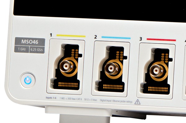
FlexChannel technology enables greater flexibility. Depending on the type of connected probe, each input can be configured as one analog channel or 8 digital channels.
Unlike previous-generation MSOs that required tradeoffs, where digital channels had lower sampling rate than analog channels, or shorter record length than analog channels. The 4 Series MSO delivers brand-new integration for digital channels. Digital channels share the same maximum sampling rate (up to 6.25 GS/s) and the same maximum record length (up to 62.5M points) as analog channels.
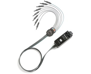
TLP058 provides 8 high-performance digital inputs. Connect multiple TLP058 probes as needed, supporting up to 48 digital channels.
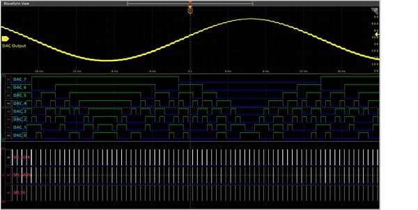
One TLP058 logic probe on Channel 2 is connected to the 8 inputs of the DAC. Note the green and blue color coding: logic 1 is green, logic 0 is blue. A second TLP058 logic probe on Channel 3 probes the SPI bus that drives the DAC. The white border indicates higher-frequency content available for zooming, and it can be acquired at a faster sweep speed in the next acquisition.
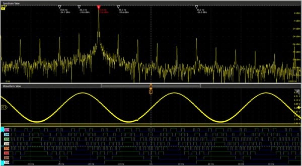
FlexChannel inputs go beyond analog and digital inputs to include Spectrum View. This Tektronix technology allows you to view both the analog view and spectrum view of all analog signals simultaneously, with independent control in each domain.
Unprecedented Signal Viewing Capability
The 4 Series MSO features an industry-leading large 13.3-inch (338 mm) display. This display also offers ultra-high resolution with Full HD resolution (1920 x 1080), enabling you to view multiple signals at one time and provides ample space for critical readings and analysis.
The viewing area is optimized to maximize the vertical space for waveforms. The right-side results bar can be hidden, allowing the waveform view to occupy the full width of the display.
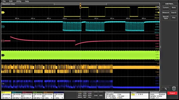
Stacked display mode makes it easy to view all waveforms while maintaining maximum ADC resolution on each input for accurate measurements.
The 4 Series MSO offers a revolutionary new stacked display mode. In the past, oscilloscopes overlay all waveforms within the same graticule, which creates a dilemma:
To view each waveform clearly, you have to scale and position each waveform vertically to avoid overlap. Each waveform only occupies a small portion of the available ADC range, so measurement accuracy is reduced.
To ensure measurement accuracy, you have to scale and position each waveform vertically to fill the entire display. Waveforms overlap with each other, making it difficult to distinguish signal details on each individual waveform.
The new stacked display mode eliminates this dilemma. When creating or deleting waveforms, it automatically adds and removes extra horizontal waveform "splits" (additional graticules). Each split uses the full ADC range. All waveforms are clearly separated from each other while still utilizing the full ADC range, achieving maximum visibility and accuracy. And all of this is done automatically when adding or removing waveforms! You can easily reorder channels in stacked display mode by dragging and dropping channel and waveform markers in the setup bar at the bottom of the display. Multiple channels can also be overlayed within a single split to simplify visual signal comparison.
The large display on the 4 Series MSO provides ample viewing area not only for signals, but also for histograms, measurement result tables, bus decode tables and more. You can easily resize and reposition each view to fit your specific application.
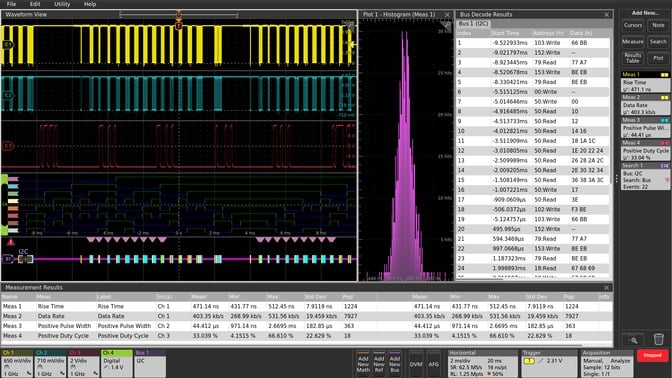 Simultaneously view 3 analog channels, 8 digital channels, 1 decoded serial bus waveform, decoded serial packet result table, 4 measurements, 1 measurement histogram, measurement result table and statistics, and search for serial bus events!
The exceptionally intuitive and user-friendly interface lets you focus on the task at hand
Settings Bar – Manage key parameters and waveforms
Waveform and oscilloscope operating parameters are displayed as a series of "badges" on the Settings Bar located at the bottom of the display. The Settings Bar provides direct access to the most commonly used waveform management tasks. With just a tap, you can:
Turn on a channel
Add a math waveform
Add a reference waveform
Add a bus waveform
Enable the optional integrated Arbitrary Waveform/Function Generator (AFG)
Enable the optional integrated Digital Voltmeter (DVM)
Results Bar – Analysis and Measurement
A simple tap on the results bar at the right side of the display gives you instant access to the most frequently used analysis tools, including cursors, measurements, search, measurement and bus decode result tables, views and notes.
DVM, measurement and search result indicators are displayed in the results bar without occupying any of your waveform viewing area. To maximize the waveform viewing area, you can collapse or restore the results bar at any time.
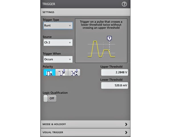 Just double-tap the item of interest on the display to open its configuration menu. In this case, double-tapping the indicator opens the trigger configuration menu.
All-New Touch Interaction
Oscilloscopes have integrated touchscreens for many years, but the touch interface experience has always been an afterthought. The 4 Series MSO features a capacitive touchscreen and delivers the industry's first oscilloscope user interface truly designed from the ground up for touch operation.
The 4 Series MSO supports all the touch gestures you already use on your phone and tablet, the same intuitive experience you would expect from a modern touch device.
Drag the waveform left/right or up/down to adjust horizontal and vertical position, or pan and zoom the view.
Use gestures to change scale or zoom in/out horizontally or vertically
Drag an item to the trash or drag it off the screen edge to delete it
Swipe from the right edge to bring up the results bar; swipe down from the top to access the menu in the top-left corner of the display
The smooth, responsive front panel controls are adjusted with familiar knobs and buttons, and mouse or keyboard can be used as a third interaction method.
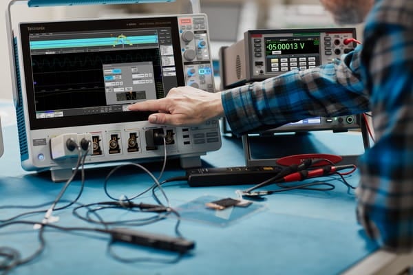
Interaction on the capacitive touch display works exactly the same as on smartphones and tablets.
Variable Font Size
Historically, oscilloscope user interfaces have been designed with fixed font sizes to optimize the display of waveforms and readings. This works well if all users have the same viewing preferences, but that is not realistic. Tektronix recognizes that users spend long hours staring at the screen. The 4 Series MSO provides users with adjustable font size preferences, ranging from a minimum of 12 point to a maximum of 20 point. When you adjust the font size, the user interface scales dynamically, so you can easily select the optimal size for your application.
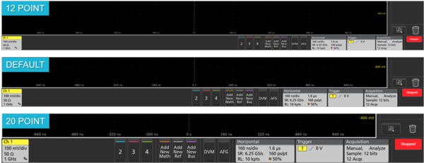
This comparison shows how the user interface scales as the font size changes. The efficient and intuitive front panel not only provides all key control functions, but also reserves ample space for a large high-definition display.
Front Panel Controls Feature Detail-Focused Design
Traditionally, the display and controls each occupy approximately half of an oscilloscope's front panel. On the 4 Series MSO, the display accounts for around 75% of the instrument's front area. To achieve this, it adopts a streamlined front panel design that retains only critical controls for simple and intuitive operation, and reduces the number of menu buttons for functions that can be accessed directly via on-screen objects.
Color-coded LED rings indicate trigger source and vertical scale/position knob assignments. The large dedicated Run/Stop/Single button is prominently located at the top right, and other functions including Force Trigger, Trigger Slope, Trigger Mode, Default Setup, Auto Setup and Quick Save are all accessible via dedicated front panel buttons.
Experience the Performance Difference
Digital Phosphor Technology and FastAcq™ High-Speed Waveform Capture
To debug design issues, you first need to detect that a problem exists. Digital Phosphor Technology and FastAcq give you deeper insight into the actual operation of your device. Its fast waveform capture rate (>500,000 waveforms per second) increases the probability of capturing common intermittent issues in digital systems, such as runt pulses, glitches, timing problems and more. To further enhance the capability of viewing intermittent events, intensity grading indicates how often intermittent transient signals occur relative to normal signal characteristics.
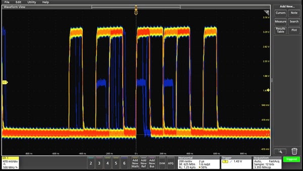
FastAcq's high waveform capture rate can catch intermittent issues common in digital designs.
Industry-Leading Vertical Resolution
The 4 Series MSO delivers outstanding performance to capture signals of interest. It minimizes the impact of unwanted noise when you need to capture high-amplitude signals while still resolving small signal details. At the core of the 4 Series MSO is a 12-bit analog-to-digital converter (ADC), which provides 16 times the vertical resolution of traditional 8-bit ADCs.
The new High Resolution mode applies a unique hardware-based finite impulse response (FIR) filter according to the selected sample rate. The FIR filter maintains maximum bandwidth for the current sample rate, prevents aliasing when available bandwidth exceeds the selected sample rate, and eliminates noise from the oscilloscope amplifier and ADC. High Res mode provides a minimum 12-bit vertical resolution across all sample rates, and extends up to 16-bit vertical resolution at sample rates ≤125 MS/s.
A new lower-noise front-end amplifier further improves the 4 Series MSO's ability to resolve fine signal details.
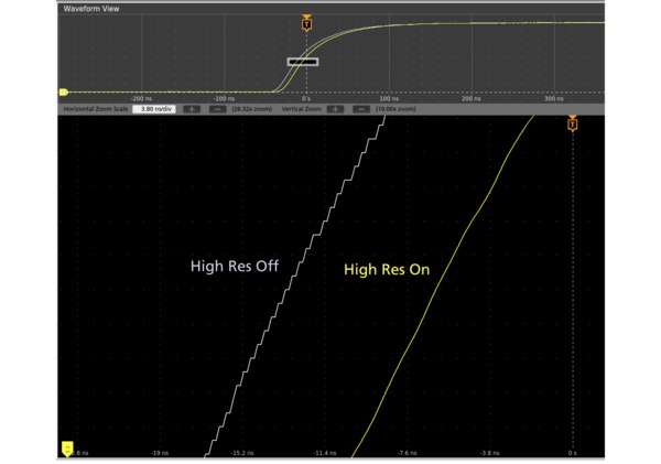
The 4 Series MSO's 12-bit ADC and new High Resolution mode achieve industry-leading vertical resolution.
Trigger
Finding a circuit issue is just the first step. Next, you must capture the corresponding event to identify the root cause. The 4 Series MSO provides a complete set of advanced trigger functions, including:
Runt
Logic
Pulse Width
Window
Timeout
Rise/Fall Time
Setup and Hold Violation
Serial Packet
Parallel Data
Sequence
Video
Visual Trigger
RF & Time (Optional)
With a maximum record length of up to 62.5 M points, you can capture many corresponding events in a single acquisition, even thousands of serial packets. It also delivers high resolution to zoom in on fine signal details and record reliable measurement data.
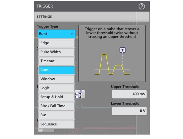
Various trigger types in the trigger menu and context-sensitive help make it easier to isolate the event of interest.
Visual Trigger – Quickly Find the Signals You Care About
Locating the right period on a complex bus can take hours of collecting and sorting thousands of acquisitions to find the event you care about. Defining triggers to isolate the desired events can speed up debugging and analysis work.
Visual Trigger extends your instrument's triggering capability by scanning every waveform acquisition and comparing it to on-screen regions (geometric shapes). You can use a mouse or touchscreen to create an unlimited number of regions, and specify the desired trigger behavior using various shapes (triangle, rectangle, hexagon or trapezoid). Once shapes are created, you can edit them interactively to create custom shapes and the ideal trigger condition. After defining multiple regions, you can use Boolean logic formulas to set up complex trigger conditions with on-screen editing.
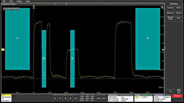
Visual trigger regions isolate the events you care about and only capture the events you want to view, saving you time.
By only triggering on the most important signal events, Visual Trigger reduces the number of acquisitions and the manual effort required to search, saving you hours of time. You can find key events and complete debugging and analysis in seconds or minutes. Visual Trigger can even be used across multiple channels to further debug and troubleshoot complex system faults.
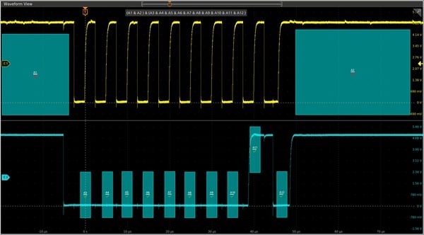
Multi-channel triggering. Visual trigger regions can be tied to events across multiple channels, for example, trigger on a certain burst width on ch
