
DeTech N9010B EXA Signal Analyzer: A Full Frequency Testing Solution from R&D to Production
2026-05-25
Keysight N9010B EXA Signal Analyzer: A Full-Band Test Solution from R&D to Production
In the development process of RF and microwave products, the signal analyzer is the core tool for verifying designs, debugging problems, and meeting compliance requirements. However, test requirements differ significantly across stages — early R&D demands high phase noise performance to capture weak signals, production lines place greater emphasis on measurement speed and repeatability, while maintenance and certification phases require wide frequency coverage and standardized measurement functions. How can these often conflicting needs be balanced within a limited equipment budget? The Keysight N9010B EXA signal analyzer, as the "cost-effective" representative of the X-Series, offers a path worth considering.
I. Product Series Overview: Six Frequency Band Versions to Choose From as Needed
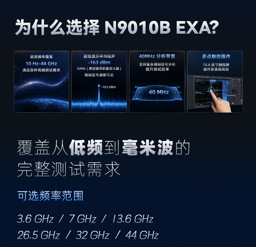
The N9010B EXA belongs to the Keysight X-Series signal analyzer family, positioned between the basic model (CXA) and the high-performance model (PXA), with its core balance point being measurement capability versus acquisition cost. The series is divided into six standard models based on maximum input frequency:
Model | Frequency Range (DC-coupled) | Typical Application Fields |
N9010B-503 | 10 Hz – 3.6 GHz | Consumer electronics, IoT, VHF/UHF communications |
N9010B-507 | 10 Hz – 7 GHz | 2.4G/5G Wi-Fi, ISM (industrial, scientific, medical) bands |
N9010B-513 | 10 Hz – 13.6 GHz | Satellite downlinks, C-band radar, 5G Sub-6 GHz |
N9010B-526 | 10 Hz – 26.5 GHz | Military communications, X/Ku-band radar, automotive radar |
N9010B-532 | 10 Hz – 32 GHz | Ka-band satellites, millimeter-wave research |
N9010B-544 | 10 Hz – 44 GHz | Millimeter-wave communications, automotive radar, materials testing |
All of the above models use the same software and hardware architecture; the only differences lie in the front-end microwave components and the LO multiplier chain. For most organizations engaged in civilian wireless communications (up to 26.5 GHz), the N9010B-526 offers the broadest coverage capability and the most outstanding cost-performance ratio.
II. Core Parameters: The Foundation of Real Test Capability
The following technical specifications are excerpted from the Keysight official specifications guide (N9010-90071, Edition 1, 2025), with data verified by factory statistics.
2.1 Frequency and Sweep Performance
· Frequency readout accuracy: ±(marker frequency × frequency reference accuracy + 0.25% × span + 5% × RBW + 2 Hz + 0.5 × horizontal resolution)
· Counter accuracy: ±(marker frequency × frequency reference accuracy + 0.100 Hz), with 0.001 Hz resolution
· Span accuracy: ±0.25% × span in sweep mode; ±0.10% × span in FFT mode
· Sweep points: 1 to 100,001 points configurable
For scenarios requiring precise measurement of carrier offsets or adjacent channel spacing, the built-in frequency counter can control errors to the 0.1 Hz level, far superior to the ordinary spectrum sweep mode.
2.2 Amplitude and Noise Floor
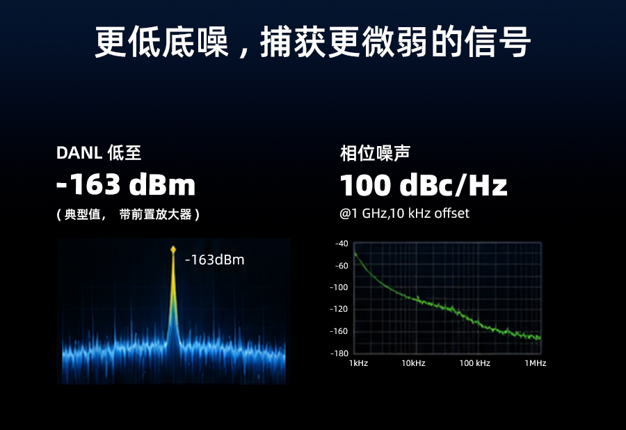
· Displayed average noise level (DANL): typical values (1 Hz RBW, 20-30°C, preamplifier off)
10 MHz – 2.1 GHz: -150 dBm
2.1 – 3.6 GHz: -149 dBm
7 – 13.6 GHz: -147 dBm
20 – 26.5 GHz: -140 dBm
· With preamplifier enabled (option P26): typical value -165 dBm for 10 MHz – 2.1 GHz
· Absolute amplitude accuracy(10 dB attenuation, -10 to -50 dBm signal, 1 Hz≤RBW≤1 MHz):
Under 20-30°C conditions: ±0.27 dB (95% confidence level)
Full temperature range (0-55°C): ±0.43 dB + frequency response
This noise floor level means that even when measuring weak spurious signals below -150 dBm, an effective signal-to-noise ratio can still be maintained. Combined with option NF2 (noise floor extension), the effective DANL in the 1.8 GHz intermediate band can be further reduced to -156 dBm (preamplifier off) or -170 dBm (preamplifier on) — which is especially critical for base station receiver sensitivity testing.
2.3 Phase Noise (1 GHz Carrier)
· 10 kHz offset: -107 dBc/Hz (typical)
· 100 kHz offset: -115 dBc/Hz (typical)
· 1 MHz offset: -134 dBc/Hz (typical)
Compared with competitors in the same price range, the EXA's close-in phase noise (<100 Hz) is not the best, but its performance at offsets above 100 kHz is very solid, sufficient for evaluating in-band spurious and local oscillator leakage of most communication transmitters.
2.4 Dynamic Range and Distortion
· Third-order intercept point (TOI)(20-30°C, 400 MHz – 3.6 GHz, preamplifier off): +14 dBm (nominal)
· Second-order harmonic intercept (SHI): +65 dBm in the 1.8 – 7 GHz band (nominal)
· 1 dB gain compression point(at mixer input): +9 dBm (20 MHz – 26.5 GHz)
· Residual responses: below -100 dBm (sweep mode)
The above specifications indicate that when measuring small spurious signals near large signals (such as the adjacent channel leakage ratio of power amplifiers), the EXA can maintain a wide linear range and is less prone to generating spurious intermodulation products.
III. Flagship Model: The Integrated Advantages of the N9010B-526 (26.5 GHz)
For the vast majority of wireless communication, IoT, industrial RF, and defense electronics applications, 26.5 GHz is a key dividing line — it covers Wi-Fi 6/6E (6 GHz), 5G Sub-6 GHz (3.5-4.2 GHz), C-band satellites (3.7-4.2 GHz), X-band radar (8-12 GHz), and Ku-band (12-18 GHz). Choosing the N9010B-526 offers the following practical values:
1. Multi-purpose frequency span in one instrument: From low-frequency spectra at 10 Hz (such as power supply noise and audio signals) straight to the 26.5 GHz millimeter-wave frontier, without the need to purchase multiple instruments for different frequency bands.
2. Optional microwave preselector bypass (option MPB): In production line testing that requires fast sweeping or extremely high repeatability, the YIG preselector can be bypassed, improving sweep speed and extending attenuator lifetime.
3. Large dynamic range analysis: At 10 kHz RBW, the adjacent channel dynamic range without noise correction is approximately -68 dBc (5 MHz offset), which improves to -73 dBc with noise correction enabled — meeting 3GPP's strict test limits for base station ACLR.
4. Flexible I/Q capture capability: Standard 25 MHz analysis bandwidth (option B25), upgradeable to 40 MHz (option B40), combined with a memory of up to 32 million IQ sample points, capable of fully capturing 802.11ac 40 MHz waveforms for EVM analysis.
5. Integrated multi-measurement applications: By installing different application software, the same hardware can perform specialized tests such as Bluetooth, WLAN, LTE, GSM/EDGE, noise figure, phase noise, and analog demodulation, avoiding duplicate investments in multiple dedicated instruments.
IV. Typical Application Scenarios and Solutions
Scenario 1: Transmitter Verification of IoT Modules
A company developing LoRa/NB-IoT modules needs to measure output power, frequency error, and adjacent channel rejection ratio. Using the EXA's "one-button power suite" measurements (Channel Power, ACP, OBW), operators can obtain a specification-compliant report within 5 seconds without in-depth RBW/VBW settings. The instrument's 10 ms-class ACP measurement transfer time (Fast method) also ensures the pacing of batch production line testing.
Scenario 2: Downlink Spurious Investigation of 5G Small Cells
When a 5G small cell transmits at 3.5 GHz, its second harmonic falls at 7 GHz, which is precisely within the coverage range of the EXA-526. Using option P26 (preamplifier) and the higher-order harmonic measurement function, harmonic components below -110 dBm can be read directly. Combined with automatic comparison against the limit lines of the spectrum emission mask (SEM), it can be instantly determined whether the 3GPP TS 38.141 limits are exceeded.
Scenario 3: Envelope Analysis of Radar Pulse Signals
For pulse-modulated radar, it is necessary to measure pulse rise/fall times, top flatness, and intra-pulse frequency modulation. The EXA's zero-span mode combined with video triggering and gated sweep can capture time spans from 1 μs to 6000 s with time accuracy of ±0.01%. Additionally, option YAS (Y-axis screen video output) can send the demodulated envelope signal as an analog voltage to an oscilloscope, facilitating joint debugging with the radar system timing.
Scenario 4: Integrated Noise Figure and Phase Noise Measurement
In the past, noise figure measurement required dedicated noise sources and instruments. However, after installing option NFE (noise floor extension) and the N9069EM0E noise figure measurement application, the EXA can use the built-in calibration process to perform full-band sweeps of amplifier gain and noise figure. Phase noise measurement (N9068EM0E) also requires no external phase discriminator, directly achieving high-sensitivity results based on cross-correlation algorithms, with measurement accuracy better than ±0.61 dB at 1 GHz carrier, 10 kHz offset.
V. Companion Software and Accessories — Extended Value
Software/Option | Model | Core Functions |
Analog demodulation | N9063EM0E | FM/AM/PM demodulation, audio filters, SINAD/THD distortion measurement |
Phase noise | N9068EM0E | Log plots, RMS jitter, residual FM, frequency offsets from 1 Hz to (maximum frequency - carrier) |
Noise figure | N9069EM0E | Gain/noise figure measurement, built-in uncertainty calculator |
Bluetooth measurement | N9081EM0E | Supports BR/EDR/LE, output power, modulation characteristics, initial carrier tolerance |
WLAN measurement | N9077EM0E | 802.11a/b/g/n/ac/af/ah, EVM floor of -47 dB (20 MHz, 5 GHz) |
Electronic attenuator | Option EA3 | 0-24 dB, 1 dB steps, improved repeatability and lifetime (below 3.6 GHz only) |
Precision frequency reference | Option PFR | Aging rate ±1×10⁻⁷/year, temperature stability ±5×10⁻⁸ (full temperature range) |
The hardware front end also retains two practical physical interfaces: the probe power supply port (+15 V / -12.6 V) can directly drive active probes; the 28 V pulse output on the rear panel is designed specifically for the Keysight SNS series noise sources, enabling automated Y-factor measurements.
VI. Comparative Reference: Brief Differences from Similarly Positioned Instruments
Since the specific data of products from different brands involves constantly updated technical parameters, only a general comparison based on publicly available historical data is provided here (no specific competitors are named; this is for technical reference only). Among economical spectrum analyzers in the same price range, some competitors' phase noise at 10 kHz offset often falls between -95 and -100 dBc/Hz, while the N9010B-526 achieves -107 dBc/Hz, which is more advantageous for in-channel blocking tests. In addition, the EXA's standard 25 MHz analysis bandwidth and upgradeable 40 MHz bandwidth typically require competitors to pay higher option costs to obtain comparable instantaneous bandwidth. In terms of absolute amplitude accuracy, the EXA's ±0.27 dB at 95% confidence level (below 3.6 GHz) is at the leading level among similar products, which is attributed to Keysight's long-term investment in digital IF calibration algorithms.
Of course, some competitors also have models that excel in interface operation habits or dynamic range in specific frequency bands. Therefore, the final selection should be comprehensively evaluated based on your own maximum frequency, measurement speed requirements, and compatibility with existing test systems.
VII. Summary and Further Support
The N9010B EXA signal analyzer series, with its clear product hierarchy, rigorously factory-verified technical specifications, and the measurement application ecosystem common to the X-Series, helps engineers reduce errors and repeated learning costs caused by instrument changes from design verification to mass production testing. Among them, the N9010B-526 covers the main frequency bands from low-frequency control signals to the 26.5 GHz millimeter-wave frontier, making it a reliable partner for most laboratories and production lines.
If you are evaluating signal analysis equipment, need a more detailed uncertainty analysis for specific frequency bands or measurement items, or wish to experience a demo unit with actual options installed, please feel free to communicate with us at any time. We can provide targeted configuration recommendations based on your device under test type (e.g., 5G FR1, Wi-Fi 7, automotive radar, or military frequency-hopping radios), and assist in understanding the test conditions and limitations behind the specifications.
